What Is the Standard Wiring Diagram for a Facial Recognition Turnstile?
When deploying facial recognition turnstile systems, many enterprises focus on device aesthetics, recognition speed, or algorithmic capabilities, yet often overlook a critical factor: the wiring structure.
In reality, the question—”What is the standard wiring diagram for a facial recognition turnstile?”—directly impacts the system’s stability, security, and long-term maintenance costs.
For system integrators and B2B procurement teams, understanding standard wiring logic not only mitigates project risks but also significantly enhances project delivery efficiency.
System Architecture at a Glance: What Components Make Up a Complete System?
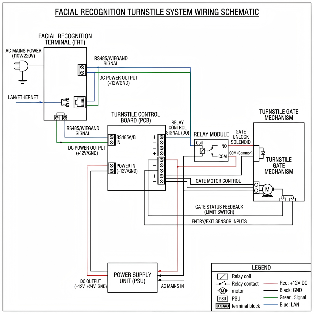
Before diving into the wiring process, let’s take a quick look at the system architecture:
[Face Recognition Terminal]
↓
[Access Control Board]
↓
[Relay Output]
↓
[Turnstile Gate]
↓
[Power Supply Unit]
The method of connection between each of these modules constitutes the core of the wiring diagram.
When setting up your turnstile, consider integration with facial recognition access control systems to improve identity verification and security.
Standard Wiring Diagram: Core Components (Layer-by-Layer Breakdown)
① Power Supply System
The standard configuration typically includes:
12V / 24V DC Power Supply
UPS Backup Power Supply (Optional)
Connection Method:
Power Supply → Control Board
Power Supply → Facial Recognition Terminal
Power Supply → Turnstile Drive Module
It is recommended to use an independent power supply to prevent interference.
Wiring diagrams are also relevant when connecting digital LOTO systems:
👉 Digital Lockout Tagout (LOTO) System
② Face Recognition Terminal Connection
Terminals typically connect via the following methods:
TCP/IP (Network Communication)
RS485 (Industrial Communication)
Wiegand Interface (Traditional Access Control Protocol)
TCP/IP is recommended to facilitate remote management and upgrades.
③ Control Board and Relay Output
This is the most critical section of the wiring diagram:
NO (Normally Open)
NC (Normally Closed)
COM (Common Terminal)
Connection Logic:
COM → Power Supply
NO → Turnstile Control Signal Input
Upon Successful Recognition:
Relay Closes → Turnstile Opens
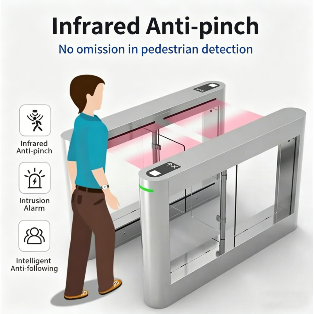
④ Turnstile Drive Module
Upon receiving signals, the turnstile executes the following actions:
Gate Opening
Gate Closing
Anti-tailgating Detection
Typical Interfaces:
Gate Open Signal Input
Infrared Detection Interface
Emergency Gate Open Interface
Standard Wiring Procedure (Step-by-Step)
To provide a more intuitive understanding of the standard wiring diagram for a facial recognition turnstile, we will outline the process in a step-by-step manner:
Step 1: Connect the Power Supply
Ensure a stable power supply for all devices.
Step 2: Connect the Facial Recognition Terminal to the Control Board
Use either Wiegand or TCP/IP protocols.
Configure the communication parameters.
Step 3: Connect the Relay to the Turnstile
Connect the COM terminal to the power source.
Connect the NO terminal to the gate-opening signal input.
Step 4: Test Signal Interconnection
Perform a facial recognition test scan.
Verify the gate-opening response.
Step 5: System Integration and Commissioning
Connect to the backend management system.
Configure user permissions.
Common Wiring Errors (Pitfalls in 90% of Projects)
❌ Power Supply Grounding Issues
Leads to device instability or damage.
❌ Incorrect Relay Wiring (NO/NC)
Results in:
Door remaining constantly open
Inability to open the door
❌ Signal Interference
Especially prevalent in factory environments.
Solutions:
Use shielded cables
Provide independent power supplies
Specific Requirements for Industrial-Grade Deployment
In factory environments or large-scale projects, wiring diagrams require further optimization:
Interference Suppression Design
Shielded Cabling
Grounding Systems
Safety Interlocks
Fire Alarm Integration
Emergency Power Cut-off and Gate Release
Multi-Device Synchronization
Interlinked Turnstiles
Central Control System Integration
From a Manufacturing Perspective: Why Do Different Manufacturers Use Different Wiring Methods?
This is a crucial point that B2B clients must understand.
Different manufacturers vary in the following aspects:
Control board design
Interface protocols
Voltage standards
Therefore:
✔ Always obtain the wiring diagram provided by the manufacturer.
✔ Do not rely solely on generic solutions.
How to Choose a Supplier That Supports Standard Wiring?
✔ Key Evaluation Criteria
- Do they provide complete wiring diagrams?
PDF documentation
Clear wiring labels - Do they support standard protocols?
Wiegand
TCP/IP
RS485 - Do they support OEM customization?
Interface expansion
Custom control logic - Technical Support Capabilities
Remote debugging
Engineering guidance
Industry Standards and References:https://www.securityindustry.org
FAQ
What is the standard wiring diagram for a facial recognition turnstile?
It is a structured connection layout linking the face recognition terminal, control board, relay, and turnstile for automated access control.
Which interface is best for connection?
TCP/IP is recommended for modern systems due to flexibility and remote management capabilities.
What happens if the relay is wired incorrectly?
The turnstile may fail to open or remain unlocked continuously.
Can the system work during power failure?
Yes, with a UPS or emergency open mechanism.
Is professional installation required?
Yes, especially for industrial environments with complex wiring needs.
Wiring Is Not a Detail—It Is the Core of the System
Understanding “what constitutes the standard wiring diagram for a facial recognition turnstile” is not merely a technical matter; it is the key to project success.
A well-designed wiring scheme delivers:
Enhanced system stability
Reduced maintenance costs
More secure access control